
Product Introduction:
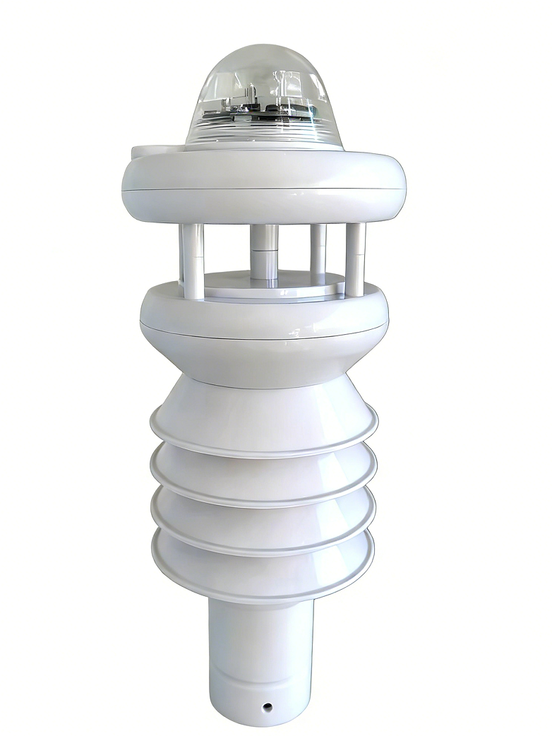
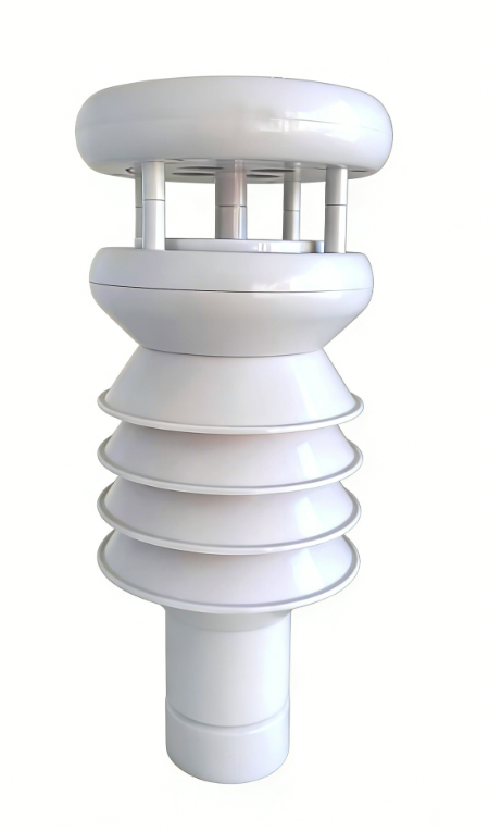
This integrated weather station is an intelligent, ultra-lightweight meteorological monitoring device employing miniaturized integration technology. Adopting a modular design concept, it can simultaneously monitor multiple meteorological and environmental parameters. The device integrates cutting-edge technologies such as ultrasonic wind measurement, optical sensing, and digital signal processing, achieving all-weather, high-precision data acquisition through multi-sensor collaborative operation. The product design fully considers adaptability to harsh outdoor environments, achieving an IP65 protection rating and stable operation in extreme temperatures ranging from -40℃ to + 70 ℃, meeting the meteorological monitoring needs of various fields such as agriculture, environmental protection, transportation, and scientific research.
Application areas:
Features:
1、Mobile monitoring revolution : 80% weight reduction
2、- low power design: 40-60mA
3、High integration and cost control: Cost reduction of 60%
4、Multiple parameter combinations offer diverse and flexible options.
5、Supports customizable rainfall intensity time.
Monitoring parameters:
Monitoring parameters | range | resolution | Accuracy |
wind direction | 0~359° | 1° | ±1° |
wind speed | 0~40m/s | 0.1m/s | ±0.1+0.03Vm/s |
Ambient temperature | -40~125℃ | 0.1℃ | ±0.2℃ (-40~0℃) |
±0.2℃ (0~65℃) | |||
±0.2℃ (65~125℃) | |||
Daily maximum temperature | -40~125℃ | 0.1℃ | Calculated value |
Daily minimum temperature | -40~125℃ | 0.1℃ | Calculated value |
Ambient humidity | 0~100%RH | 0.1%RH | ±1%RH (0~10%RH) |
±1.5%RH (10~90%RH) | |||
±2%RH (90~100%RH) | |||
Dew point temperature | -40~125℃ | 0.1℃ | Calculated value |
Atmospheric pressure | 300~1100hpa | 0.1 hpa | ±0.1hpa |
rainfall | 0~9999mm | 0.2mm | ±2% |
Rain intensity | 0~9999mm/min | 0.1 mm/min | ±2% |
Total radiation | 0~2000 W/m² | 1 W/m² | ≤2% |
Sunshine hours | 0~24h | 0.1h | ≤2% |
Ultraviolet radiation | 0~300 W/㎡ | 1 W/㎡ | ≤2% |
Photosynthetic efficiency | 0~2500umol/㎡s | 1umol/㎡s | ≤2% |
noise | 30~130dB | 0.1 dB | ±0.5dB |
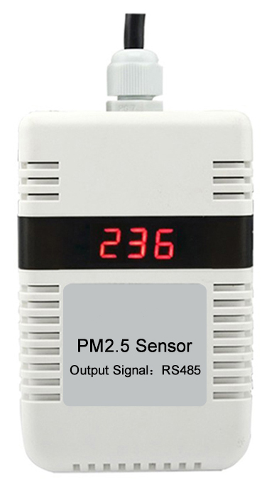
PM2.5 | 0~2000 ug/m³ | 1 ug/m³ | ±10ug/m³ |
PM10 | 0~2000 ug/m³ | 1 ug/m³ | ±10ug/m³ |
Technical parameters:
name | parameter |
Operating temperature | -40~70℃ |
Operating humidity | 0~100%RH (non-condensing) |
Operating voltage | DC12-24V |
Power consumption | 40~60mA |
Product Dimensions | Φ116mm×295mm (maximum size) |
weight | 500g |
Extended storage | Supports 32GB SD cards with configurable storage cycles and hot-swappable functionality. Files can be opened directly in Excel format. (Optional) |
Communication interface | RS485 standard Modbus address baud rate adjustable |
Power outage time saving | support |
GPS data positioning | Supports onboard integration (optional) |
4G data communication | Supports onboard integration (optional) |
Bluetooth data communication | Supports onboard integration (optional) |
Integrated weather station connector | Optional |
Product installation diagram:
1. Installation diagram for Method 1 (with connectors):

Connector dimension drawing

Note: Ensure the integrated weather station is perpendicular to the ground. The arrow at the top of the integrated weather station should point due north during installation.
Friendly reminder: If you encounter any problems during installation, please contact our after-sales staff for remote guidance .
Wiring instructions:
Refer to the table below and connect the weather station correctly according to the corresponding connector wiring definitions:
Signal name | Line color | Output/Signal |
Power supply + | red | Power input + (DC 12-24 V) |
Power supply - | black | Power input - or GND |
Signal output | yellow | RS485-A |
Signal output | green | RS485-B |
Communication protocol:
9.1 Communication Parameters
Baud rate—9600bps , configurable default, modifiable ; Data bits—8 bits; Parity bit—NO (no parity); Stop bits—1 bit e; Communication address range: 1-247, configurable (default is 1); Standard MODBUSRTU protocol.
9.2 The integrated meteorological station list is shown in the table below:
Register address | Feature name | Number of registers | Decimal places | unit | Data types |
0x0000 | wind direction | 1 | 0 | ° | Unsigned integer |
0x0001 | wind speed | 1 | 1 | m/s | Unsigned integer |
0x0002 | temperature | 1 | 1 | ℃ | Signed integers |
0x0003 | highest temperature | 1 | 1 | ℃ | Signed integers |
0x0004 | minimum temperature | 1 | 1 | ℃ | Signed integers |
0x0005 | humidity | 1 | 1 | %RH | Unsigned integer |
0x0006 | Dew point | 1 | 1 | ℃ | Signed integers |
0x0007 | air pressure | 1 | 1 | hPa | Unsigned integer |
0x0008 | rainfall | 1 | 1 | mm | Unsigned integer |
0x0009 | Rainfall intensity in X minutes or X hours rainfall intensity | 1 | 1 | mm/s or mm/h | Unsigned integer |
0x000a | Total radiation | 1 | 0 | w/m² | Unsigned integer |
0x000b | Sunshine hours | 1 | 1 | h | Unsigned integer |
0x000c-0x000d | Illumination | 2 | 0 | Lux | Unsigned integer |
0x000e | Ultraviolet radiation | 1 | 0 | w/m² | Unsigned integer |
0x000f | Photosynthetic efficiency | 1 | 0 | μmol/m²s | Unsigned integer |
0x0010 | noise | 1 | 1 | db | Unsigned integer |
0x0011 | PM2.5 | 1 | 0 | μg/m3 | Unsigned integer |
0x0012 | PM10 | 1 | 0 | μg/m3 | Unsigned integer |
0x0020 | years | 1 | 0 |
| BCD |
0x0021 | Daily | 1 | 0 |
| BCD |
0x0022 | Seconds | 1 | 0 |
| BCD |
Communication Protocol:
10.1 Reading Data
1. Data Frame - Transmission: Host Computer -> Integrated Weather Station
name | byte | data |
Integrated Weather Station Address | 1 | 0xXX: Address of integrated weather station |
Function code | 1 | 0x03: Read integrated weather station data function code |
Data area --- High byte of register address | 1 | 0xXX: High byte of register address |
Data area --- Low byte of register address | 1 | 0xXX: Low byte of register address |
Data area --- Number of registers read (high byte) | 1 | 0xXX: Number of registers read (high byte) |
Data area --- Number of registers read (low byte) |
1 | 0xXX: Number of registers read (low byte) One length represents two bytes of register data. |
CRC checksum | 2 | CRC check |
2. Data Frame - Response: Integrated Weather Station -> Host Computer
name | byte | data |
Integrated meteorological address | 1 | 0xXX: Address of integrated weather station |
Function code | 1 | 0x03: Read integrated weather station data function code |
Data byte length | 1 | 0xXX: Data byte length [Read data length * 2 bytes] |
Data area --- the high byte of data in the first register | 1 | 0xXX: High byte of data in the first register |
Data area --- Low byte of data in the first register | 1 | 0xXX: Low byte of data in register 1 |
Data area --- the high byte of data in the second register | 1 | 0xXX: High byte of data in the second register |
Data area --- Low byte of data in the second register | 1 | 0xXX: Low byte of data in the second register |
... | … | … |
CRC checksum | 2 | CRC check |
Note: The data area message returned by the integrated weather station consists of 2 bytes representing the data for one channel. The order of the channel data follows the point table order attached to each integrated weather station device. Channel data can be either unsigned integer or signed integer (e.g., temperature data is signed integer data).
The following is an example based on the integrated meteorological station table:
Host computer: 01 03 00 00 00 13 04 07
Integrated Weather Station: 01 03 26 00 4A 00 23 FF F4 FF F7 FF F4 01 64 00 01 27 37 00 02 00 0B 03 E8 00 04 00 00 4E 20 00 C8 05 DC 00 50 00 28 00 32 29 F7
01 Device Address
00 4A Wind direction: 74°
00 23 Wind speed: 3.5m/s
FF F4 Temperature: -1.2℃. Since the ambient temperature is a signed integer, negative numbers are transmitted in two's complement form, i.e., the original number = the inverted two's complement + 1.
FF F7 Maximum temperature: -0.9℃
FF F4 Minimum temperature: -1.2℃
01 64 Humidity: 35.6%RH
00 01 Dew point temperature: 0.1℃
27 37 Atmospheric pressure: 1003.9 hPa
Rainfall: 0.2mm
Rainfall intensity: 1.1 mm
03 E8 Total radiation: 1000w/m²
00 04 Sunshine hours: 0.4h
00 00 4E 20 Illuminance: 20000 Lux
00 C8 Ultraviolet Radiation: 200w/m²
05 DC photosynthetic efficiency: 1500 μmol/m²s
00 50 Noise: 8dB
00 28 PM2.5: 40μg/m3
00 32 PM10: 50μg/m3
10.2 Setting the Time
1. Data Frame - Transmission: Host Computer -> Integrated Weather Station
name | byte | data |
Integrated Weather Station Address | 1 | 0xXX: Address of integrated weather station |
Function code | 1 | 0x10: Parameter setting function code |
Set the high byte of the register start address | 1 | 0x02: Set the high byte of the register (fixed) |
Set the low byte of the register start address | 1 | 0x00: Set register low byte (fixed) |
Set the number of registers (high byte) | 1 | 0x00: Number of registers (high byte) (fixed) |
Set the number of registers in the low byte. | 1 | 0x03: Number of registers (low byte) (fixed) |
Data byte length | 1 | 0x06: Data byte length (fixed) |
Data area --- year | 1 | 0xXX: Year. For example, 0x25 represents 2025. |
Data area --- Month | 1 | 0xXX: Month. For example, 0x10 represents October. |
Data area---Day | 1 | 0xXX: Day. For example, 0x22 represents the 22nd. |
Data area --- time | 1 | 0xXX: For example, 0x11 represents 11. |
Data area --- | 1 | 0xXX: points. For example, 0x54 means 54 points. |
Data area --- seconds | 1 | 0xXX: seconds. For example, 0x15 represents 15 seconds. |
CRC checksum | 2 | CRC check |
2. Data Frame - Response: Integrated Weather Station -> Host Computer
name | byte | data |
Integrated Weather Station Address | 1 | 0xXX: Address of integrated weather station |
Function code | 1 | 0x10: Parameter setting function code |
Set the high byte of the register start address | 1 | 0x02: Set the high byte of the register (fixed) |
Set the low byte of the register start address | 1 | 0x00: Set register low byte (fixed) |
Set the number of registers (high byte) | 1 | 0x00: Data length (high byte) (fixed) |
Set the number of registers in the low byte. | 1 | 0x03: Matches this byte in the received message. |
CRC checksum | 2 | CRC check |
10.3 Setting the Communication Address
1. Data Frame - Transmission: Host Computer -> Integrated Weather Station
name | byte | data |
Integrated Weather Station Address | 1 | 0xXX: Address of integrated weather station |
Function code | 1 | 0x06: Parameter setting function code |
Set the high byte of the register start address | 1 | 0x00: Set the high byte of the register (fixed) |
Set the low byte of the register start address | 1 | 0x64: Set register low byte (fixed) |
Set the number of registers (high byte) | 1 | 0x00: Number of registers (high byte) (fixed) |
Set the changed address | 1 | 0x02: Number of registers (low byte) (fixed) |
CRC checksum | 2 | CRC check |
2. Data Frame - Response: Integrated Weather Station -> Host Computer
name | byte | data |
Integrated Weather Station Address | 1 | 0xXX: Address of integrated weather station |
Function code | 1 | 0x06: Parameter setting function code |
Set the high byte of the register start address | 1 | 0x00: Set the high byte of the register (fixed) |
Set the low byte of the register start address | 1 | 0x64: Set register low byte (fixed) |
Set the number of registers (high byte) | 1 | 0x00: Number of registers (high byte) (fixed) |
Set the changed address | 1 | 0x02: Matches this byte in the received message. |
CRC checksum | 2 | CRC check |
10.4 Setting the Communication Baud Rate
1. Data Frame - Transmission: Host Computer -> Integrated Weather Station
name | byte | data |
Integrated Weather Station Address | 1 | 0xXX: Address of integrated weather station |
Function code | 1 | 0x06: Parameter setting function code |
Set the high byte of the register start address | 1 | 0x00: Set the high byte of the register (fixed) |
Set the low byte of the register start address | 1 | 0x65: Set register low byte (fixed) |
Set the number of registers (high byte) | 1 | 0x00: Number of registers (high byte) (fixed) |
Set baud rate | 1 | 0x03: Number of registers (low byte) (fixed) |
Data area --- Communication baud rate flag |
1 | 0xXX: Baud Rate Description 0x01:4800 0x02: 9600 0x03: 19200 0x04: 38400 0x05: 57600 0x06: 115200 |
CRC checksum | 2 | CRC check |
2. Data Frame - Response: Integrated Weather Station -> Host Computer
name | byte | data |
Integrated Weather Station Address | 1 | 0xXX: Address of integrated weather station |
Function code | 1 | 0x06: Parameter setting function code |
Set the high byte of the register start address | 1 | 0x00: Set the high byte of the register (fixed) |
Set the low byte of the register start address | 1 | 0x65: Set register low byte (fixed) |
Set the number of registers (high byte) | 1 | 0x00: Number of registers (high byte) (fixed) |
Set baud rate | 1 | 0x03: Matches this byte in the received message. |
CRC checksum | 2 | CRC check |
Note: The software version number is automatically reported upon startup. For example, the data content 01 03 06 01 23 20 25 12 22 crc indicates V1.23 2025.12.22.
Precautions and maintenance
1. Please check if the packaging is intact and verify that the product model matches the selected model;
2. Never connect wires while the circuit is live. Power can only be applied after the wiring is completed and checked to ensure that everything is correct.
3. Do not arbitrarily modify the components or wires that have been soldered on at the factory when using the product;
4. Lightning protection measures: The integrated meteorological station system needs to be within the lightning protection range and will also take corresponding measures to protect against the hazards of other induced lightning. During the installation process, attention should be paid to reliable and reasonable grounding to eliminate overvoltage, overcurrent and lightning magnetic pulse outside the equipment.
5. For the wiring of 220V mains power, both electrical safety and the appearance of the building where it is installed must be taken into account.
6. Users should not disassemble the sensor themselves during use, nor should they use sharp objects or corrosive liquids to contact the sensor surface to avoid damaging the product;
7. Regularly monitor and clean the Stevenson screen to check for any foreign objects covering it. Power must be disconnected during cleaning. Pay special attention to cleaning the dust on the panel and the dirt inside the aviation socket.
8. Please keep the calibration certificate and certificate of conformity safe, and return them with the product during repair.
9. During installation, the Stevenson screen must be installed perpendicular to the ground. If it is installed at an angle, rain or snow will enter during rainy or snowy weather, and the moisture will easily affect the data.


Long Press to Scan QR Code
Scan QR Code