This manual is ATMITRO User manual for the compact weather station (CC-M400 series). For any questions , please contact your dedicated sales representative :
1.3 Documentation Conventions
This manual uses the following notation conventions:
Label
Meaning
Warn
Failure to comply with these instructions may result in equipment damage or personal injury. Please be sure to follow them strictly.
Notice
Key operational points that require special attention should not be overlooked, as neglecting them may affect equipment performance or measurement accuracy.
Hint
Suggestions and instructions to help you use this product better and more efficiently
1.4 Trademarks and Copyrights
ATMITRO and related logos are registered trademarks of Chaosensor. No part of this manual may be reproduced, distributed, or quoted in any form without the company's written permission.
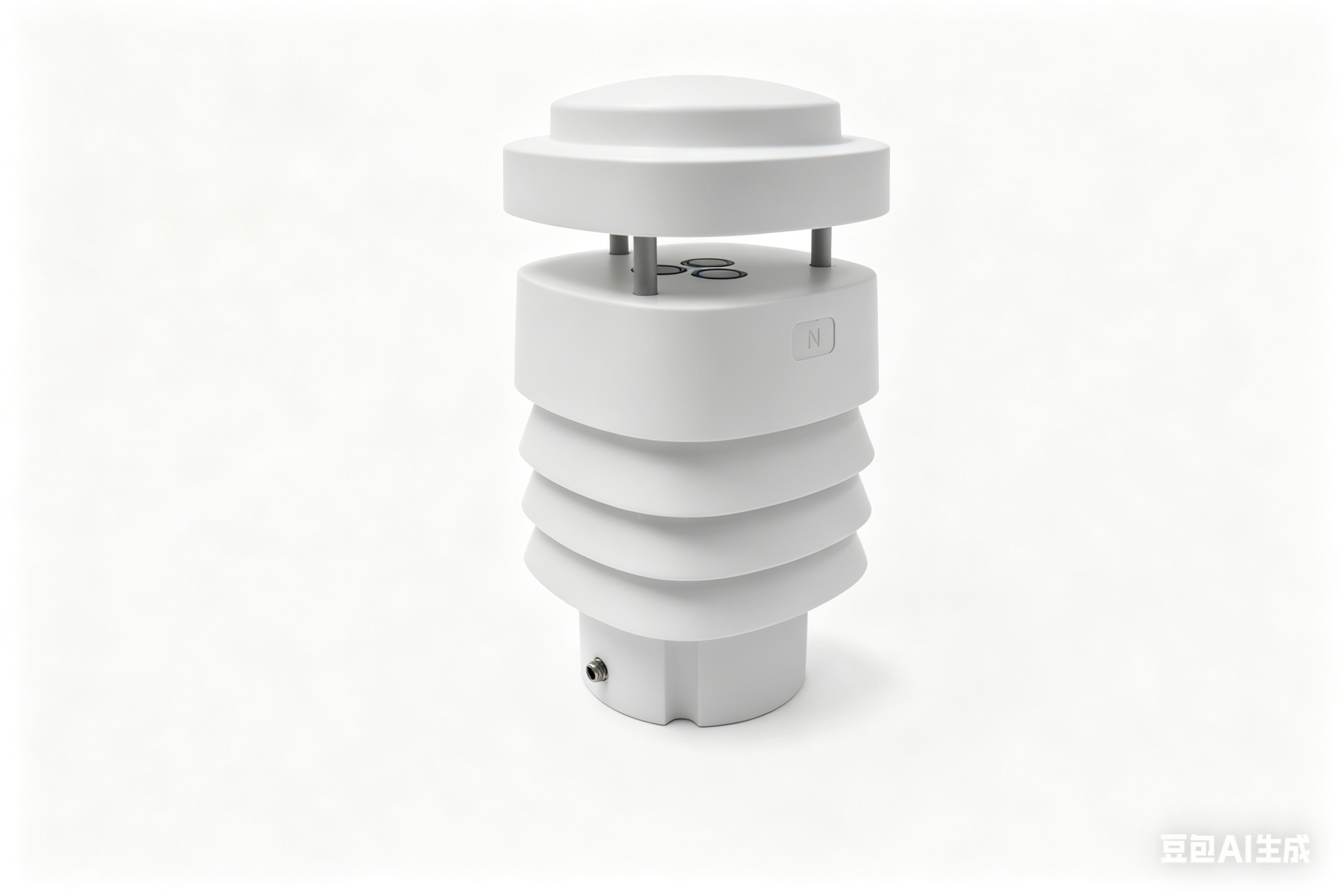
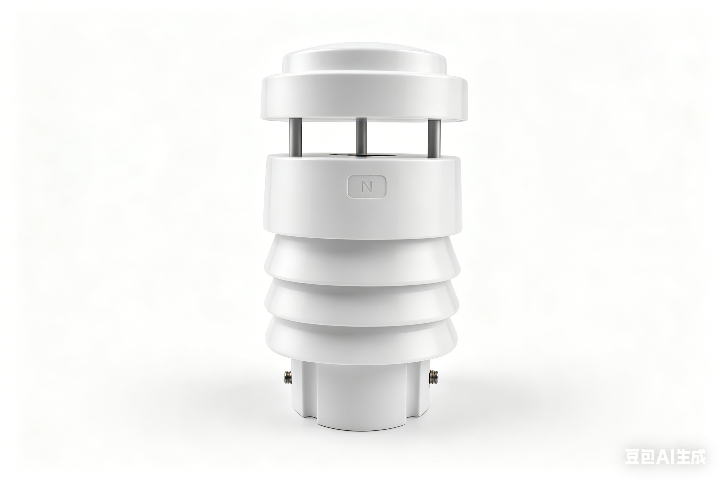
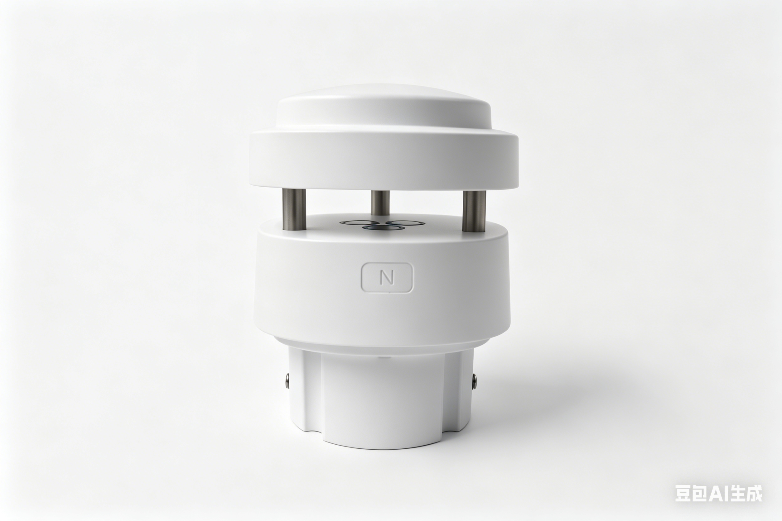
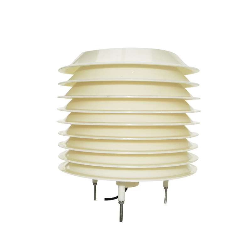
ATMITROThe compact weather station (CC-M400 series) is a highly integrated instrument designed for meteorological monitoring needs in multiple fields. It adopts an integrated structural design and can simultaneously achieve 24-hour continuous online monitoring of eight meteorological parameters: atmospheric temperature, air humidity, wind speed, wind direction, atmospheric pressure, rainfall, illuminance, and total radiation. All data can be output at once through a digital communication interface.
The product uses ultrasonic wind measurement technology and radar rainfall measurement technology. It has no moving parts, requires little maintenance, and is suitable for long-term unattended operation scenarios.
uThe radiation shield uses a special heat insulation process.
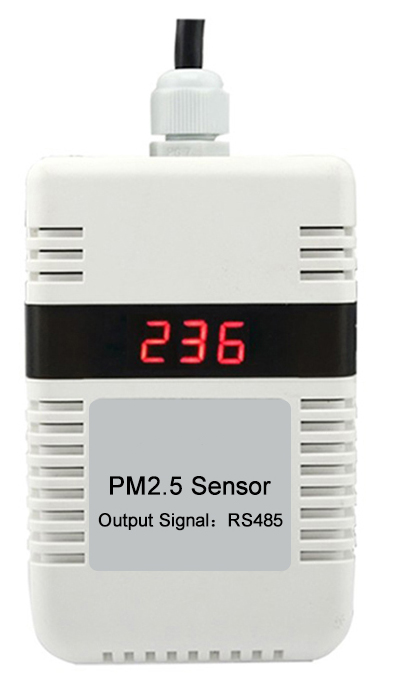
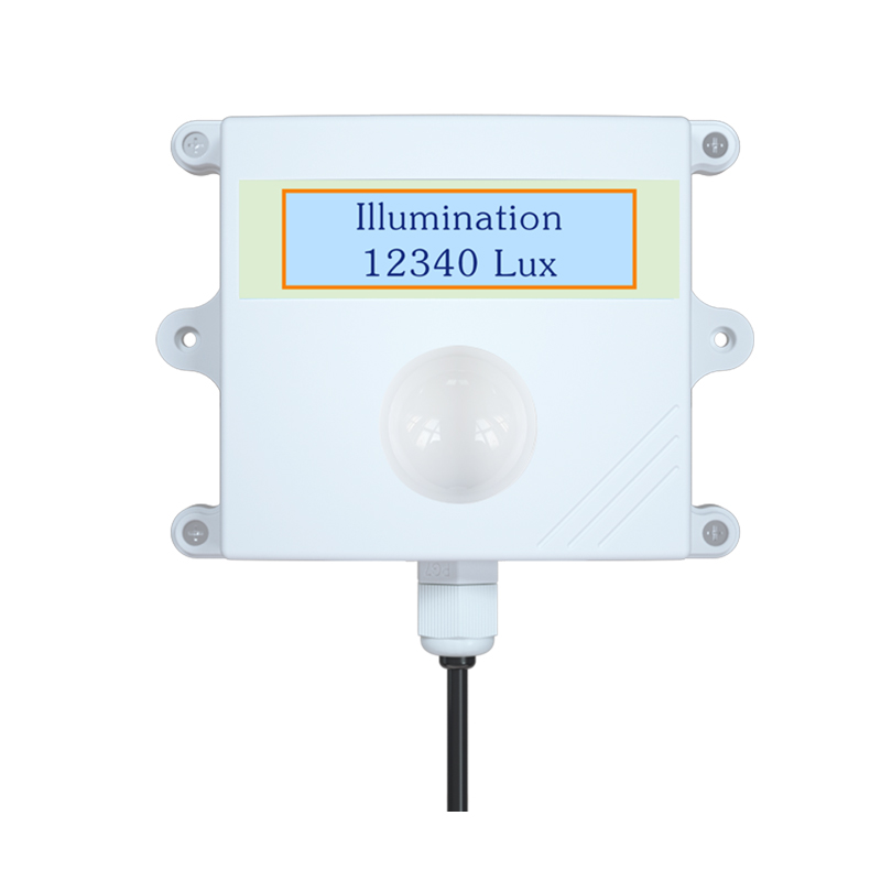
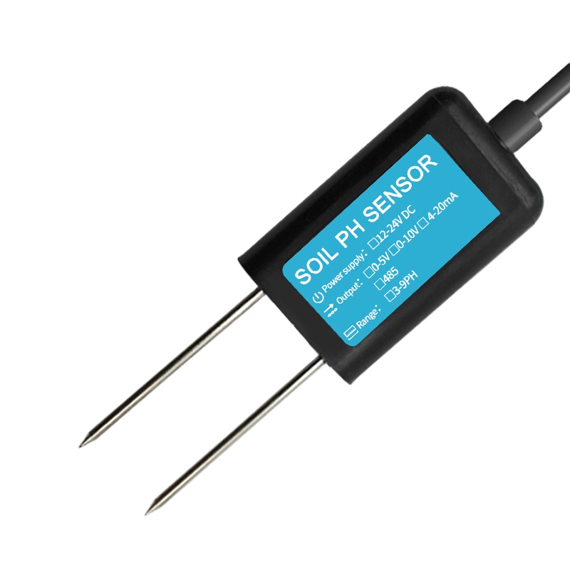
uSupports extended parameter measurement
uStandard RS485 / Modbus RTU interface
2.2 Product Technical Parameters
Monitoring parameters
Measurement range
Accuracy
Resolution
Sampling frequency
Air temperature
-40-85℃
±0.2℃ (@25℃)
0.01℃
1 Hz
Air humidity
0-100%RH
±2%RH (10%~80%RH, no condensation)
0.01%RH
1 Hz
Wind speed
0-60 m/s
±(0.5+0.05V) m/s
V represents the wind tunnel calibration wind speed (m/s).
0.01 m/s
4 Hz
Wind direction
0-359.9°
±1° (@10 m/s)
0.1°
4 Hz
Atmospheric pressure
500-1100 hPa
±0.5 hPa (@25℃, 950~1100 hPa)
0.1 hPa
1 Hz
Rainfall
0-200 mm/h
±5% (wind speed ≤ 5 m/s)
0.01 mm
1 Hz
Illumination
0-100 Klux
±2% FS
10 Lux
1 Hz
Total radiation
0-1500 W/㎡
±2%
1 W/㎡
1 Hz
Overall parameters
Specification
Operating temperature
-20℃ ~ 60℃
Output interface
RS485, Modbus RTU
Maximum output frequency
Passive mode: 1 time/second; Active mode: 1 time/minute
Power supply voltage
DC 9 ~ 24V (DC 12V recommended)
Protection level
IP65
Fixing method
Sleeve type (standard); flange type, bent plate type (optional)
Standard cable
3 meters (10 meters optional)
Note: Specifications are subject to change without notice. Please refer to the actual product and the latest manual for accurate information.
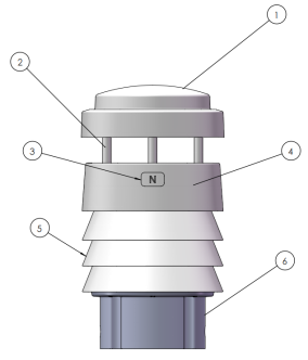
2.4 Components
The standard packaging includes the following components; please check them one by one upon receipt:
No.
Component Name
Quantity
Illustrate
1
Compact weather station main unit
1 unit
CC-M400series
2
Communication cables
1 root
Standard configuration: 3 meters, including aviation connector
3
Fixing screws
4
M6 is used for fixing the seat and locking.
Note: If you selected flanges, extension cables, or pole supports when ordering, please also check that all optional accessories are included. If any are missing or damaged, please contact sales personnel within 48 hours of receiving the goods.
Installation kit
Optional flanges are available to accommodate different installation methods.
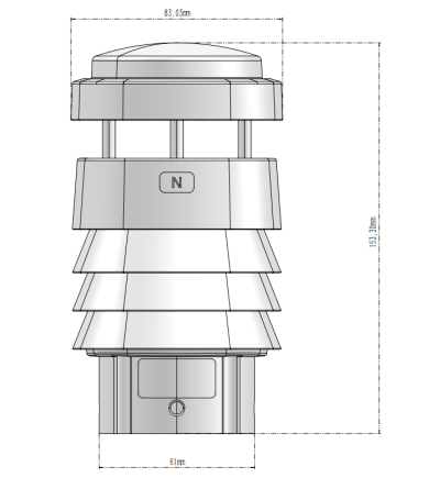
2.5 Product Dimensions
2.5.1 Product Dimension Drawing
Main external dimensions for reference:
Size items
Numerical values
Overall height
153.3 mm
Overall diameter
83.03 mm
Inner diameter of mounting bracket
49mm
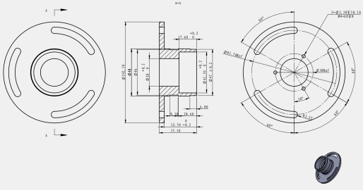
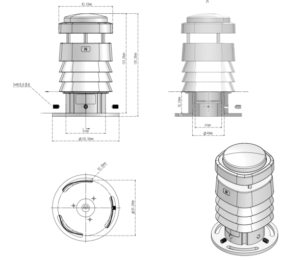
2.5.2 Product Installation Dimensions
2.6 Supporting host computer software
CC-M400 series compact weather stations. It runs on the Windows operating system and its main functions include:
uReal-time reading and display of eight meteorological parameters
uSupports data recording and export
uSupports configuration of communication parameters such as device address and baud rate.
uSupports sensor drift calibration operation
Introduction to Principles
3.1 Wind Measurement Principle
The CC-M400 series uses ultrasonic wind measurement technology, which arranges three ultrasonic probes at equal intervals on a horizontal plane. By measuring the phase change of ultrasonic waves propagating between each group of probes, wind speed and wind direction are inverted, without any mechanical rotating parts.
The specific principle is as follows: When the ambient wind speed is zero, the phase change of the ultrasonic wave along each path is zero; when there is wind, the propagation speed of the sound wave in the downwind direction increases, and the phase change decreases, while the opposite is true in the upwind direction. The sensor collects the phase change on the three paths, and after trigonometric function calculations, it obtains the horizontal wind speed and wind direction, and can simultaneously output multiple data such as instantaneous wind speed, instantaneous wind direction, average wind speed, and average wind direction.
Note: Ultrasonic wind measurement has no mechanical wear, making it suitable for long-term unattended scenarios.
3.2 Rainfall Measurement Principle
The CC-M400 series uses a small 24 GHz radar module to achieve real-time rainfall measurement. The radar module continuously emits electromagnetic waves into the air and receives the reflected signals from raindrops. It uses the Doppler effect to calculate the falling velocity and particle size distribution of the raindrops, and then calculates the real-time rainfall amount and intensity.
Compared with traditional tipping bucket rain gauges, radar rainfall measurement has the following advantages:
·Without a mechanical tipping structure, it is unaffected by blockages or evaporation.
·Real-time output of rainfall intensity, fast response speed
·It can maintain high measurement accuracy in low rainfall scenarios.
Note: Understrong wind conditions (wind speed > 5m/s), the raindrop trajectory may be deflected, which may have a certain impact on the rainfall measurement results. For accuracy, please refer to the notes in the parameter table in Chapter 2
Chapter 4 Installation Guide
4.1 Unpacking and Inspection
The equipment is usually shipped via express delivery. After receiving the goods, please follow the steps below to open and inspect the package
1.Check the outer packaging for any obvious damage or deformation. If any abnormalities are found, please take photos for record-keeping before opening the box.
2.Refer to the component list in Section 2.4 to check whether all items in the box are complete.
3.Check that the main unit of the equipment is in good condition, and that the connectors and cables are undamaged.
4.Check that the retaining sleeve and screws are complete.
Note: If any missing or damaged items are found, please contact the sales staff within 48 hours of receiving the goods and provide photos for record-keeping so that the issue can be addressed promptly.
4.2 Installation Location Selection
The choice of installation location directly affects the representativeness and accuracy of the measurement data. Please follow these principles:
1.Choose an open and representative location to avoid local microclimate interference.
2.The horizontal distance between the equipment and surrounding obstacles (buildings, trees, etc.) should be no less than 10 times the height of the obstacle.
3.Avoid installing near sources of strong electromagnetic interference (such as high-voltage lines, high-power motors, radar equipment, etc.) to prevent affecting communication stability.
4.Avoid installing near heat sources or strong radiators (such as air conditioner outdoor units, metal roofs, etc.) to prevent affecting the accuracy of temperature, humidity, and radiation measurements.
5.The installation height should follow local meteorological observation standards, generally 1.5 to 10 meters above the ground.
Note: If used for agricultural meteorology or photovoltaic power station monitoring, it is recommended to install the equipment at the same height as the crop canopy or module to obtain more representative microclimate data.
4.3 Mechanical Installation
4.3.1 Flange Installation
1.Align the optional flange with the mounting holes on the crossarm and secure it with M6 screws.
2.Place the main unit of the equipment on the flange and adjust its orientation so that the north indicator on the machine body points to true north.
3.Tighten the three fixing screws on the mounting base evenly to ensure the equipment is level and free from wobbling.
Note: The accuracy of the north direction directly affects the measurement results of the wind direction data. It is recommended to use a compass or mobile phone compass for calibration during installation.
4.3.2 Direct installation of uprights
1.Insert the main unit of the equipment onto the pole and adjust its orientation so that the north marker points due north.
2.Tighten the three fixing screws on the mounting base evenly to ensure the equipment is stable and does not wobble.
3.Confirm that the entire equipment is level.
Note: The diameter of the upright must be within the range of the equipment fixing sleeve. Please refer to the installation dimension diagram in Section 2.5.2 to confirm the matching size before installation.
4.4 Electrical Connections
4.4.1 Interface wiring diagram
The equipment comes standard with an aviation connector. When connecting, please align the groove of the male connector with the protrusion of the female connector and insert it. Then tighten the screw clockwise to ensure a reliable seal at the interface.
4.4.2 Wiring Definition
Cablecolor
Definition
Specifications
Red
Positive power supply
DC 9 ~ 24V, DC 12V recommended
Black
Negative power supply
—
Yellow
RS485 A
—
Blue
RS485 B
—
Warning: Ensure the power supply is disconnected before wiring. Do not operate while the power is on. Do not reverse the positive and negative terminals of the power supply, as this may cause permanent damage to the equipment. Do not short-circuit or connect the RS485 A/B lines incorrectly to avoid communication problems.
Chapter 5 Power and Communication Management
5.1 Power Requirements
Voltage range and power consumption
The CC-M400 series supports wide voltage DC power supply. Specific parameters are as follows:
Parameter
Specification
Power supply voltage range
DC 9 ~ 24V
Recommended power supply voltage
DC 12V
Typical power consumption
XF802/XF805:<0.2W;XF806/XF808: <0.4W
Power ripple requirements
≤ 200 mV
Warning: The power supply voltage must not exceed DC 24V. Overvoltage may cause permanent damage to the equipment. It is recommended to install a suitable surge protection device in the power supply line, especially for long-term outdoor deployment scenarios.
Note: If using a solar power system, it is recommended to configure a battery pack to ensure continuous power supply at night and on cloudy days. The controller output voltage must be stable within the range of DC 9 ~ 24V.
5.2 Communication Interface Configuration
5.2.1 Modbus RTU Parameters
The device's default communication parameters are as follows:
Note: Baud rate changes must be executed via Modbus write commands and will take effect immediately. The host computer must be synchronized to the same baud rate for communication to continue. Non-professionals should not arbitrarily change the baud rate to avoid communication interruption. See Section 6.3.7 for specific modification commands .
5.2.2 Data Frame Format
The CC-M400 series uses the standard Modbus RTU frame format, and the data frame structure is as follows:
Fields
Length
Illustrate
Device address
1 byte
Identify target device
Function code
1 byte
03: Read input register; 06: Write single register
Register address
2 bytes
High byte first, low byte last
Number of data/registers
2 bytes
High byte first, low byte last
CRC16 check
2 bytes
Low byte first, high byte last
Note: The CRC16 check byte order is the reverse of the register address byte order, with the low byte first and the high byte last. Please pay attention to this distinction during host computer development to avoid check errors.
5.3 Wiring Diagram
5.3.1 Power and Communication Terminal Definitions
Typical wiring methods are as follows:
Device side
Connected to
Red (positive powersupply)
DC power supply positive output terminal
Black (negative power supply)
DC power supply negative output terminal
Yellow (RS485 A)
Host computer/data acquisition unit RS485 A terminal
Blue (RS485 B)
Host computer/data acquisition unit RS485 B terminal
5.3.2 Shielding and Grounding Treatment
In outdoor long-distance cabling scenarios, the following shielding and grounding measures are recommended to ensure communication stability:
1.Shielded twisted pair (STP) cable is used as the RS485 communication cable, with the shield grounded at one end.
2.The RS485 bus is recommended to use a daisy-chain topology, avoiding star connections.
3.It is recommended to install a 120Ω terminating resistor at each end of the bus, especially when the communication distance exceeds 100 meters or the number of nodes is large.
4.It is recommended that the equipment installation pole be properly grounded for lightning protection, and the grounding resistance should not exceed 4Ω.
5.When laying cables in conduits, high-voltage and low-voltage cables should be run in separate conduits with a spacing of not less than 200 mm.
Warning: Outdoor wiring must be properly waterproofed. All joints and junction boxes must meet the corresponding protection level requirements to avoid damage to equipment or wiring due to water ingress.
Chapter 6 Communication Protocol
6.1 Communication Parameters
The CC-M400 series uses the standard Modbus RTU protocol, and the factory default communication parameters are as follows:
Parameter
Default value
Baud rate
9600 bps
Data bits
8-bit
Stop bit
1 person
Check bit
none
Device address
0xFF
6.2 Agreement Description
6.2.1 CRC Description
This protocol uses the Modbus standard CRC16 checksum algorithm. The CRC16 checksum is 2 bytes, with the low byte first and the high byte last, as per Modbus specifications. The host computer must calculate and append a correct CRC16 checksum before sending each instruction; the device will not respond to instructions with incorrect checksums.
6.2.2 Error Code Specification
The device handles all erroneous commands (including CRC16 checksum errors) without returning an error code. If the host computer does not receive a return data within 200 ms after the command is sent, it can determine that the command transmission has failed and can resend the command.
6.2.3 Standard Modbus Register Description
Note: In Modbus instructions, register addresses and quantities are in 2-byte (16-bit) units, with the high byte first and the low byte last, not in single-byte (8-bit) units. Register addresses and quantities must be within the range specified in this manual; otherwise, the device output will be unpredictable. The system supports a minimum polling cycle of 1 second.
Input register (Function code 03 Read)
Register address
Operate
Content
Conversion Explanation
0x0001-0x0008
Read-only
Reserve
—
0x0009
Read-only
Air temperature
Original value ÷ 100 − 40, unit: °C. For example, 0x1B00 = 6912, 6912 ÷ 100 − 40 = 29.12 °C.
0x000A
Read-only
Air humidity
Original value ÷ 100, unit: %RH. For example, 0x1603 = 5635, 5635 ÷ 100 = 56.35%RH
0x000B
Read-only
Atmospheric pressure
Original value ÷ 10, unit hPa. For example, 0x2784 = 10116, 10116 ÷ 10 = 1011.6 hPa
0x000C
Read-only
Wind speed
Original value ÷ 100, unit: m/s. For example, 0x0125 = 293, 293 ÷ 100 = 2.93 m/s
0x000D
Read-only
Wind direction
Original value ÷ 10, unit: degrees, north is 0°. For example, 0x0C14 = 3092, 3092 ÷ 10 = 309.2°
0x000E
Read-only
Cumulative rainfall
Original value ÷ 100, unit: mm. For example, 0x0016 = 22, 22 ÷ 100= 0.22mm.
0x000F
Read-only
Total radiation
The original value is the radiation intensity, measured in W/m². For example, 0x0172 = 370 W/m².
0x0010
Read-only
Illumination
Original value ÷ 100, unit: Klux. For example, 0x0123 = 291, 291 ÷ 100 = 2.91 Klux.
......
0x0015
Read-only
Average wind speed
Original value ÷ 100, unit: m/s. For example, 0x0125 = 293, 293 ÷ 100 = 2.93 m/s
0x0016
Read-only
Average wind direction
Original value ÷ 10, unit: degrees, north is 0°. For example, 0x0C14 = 3092, 3092 ÷ 10 = 309.2°
The following example reads wind speed data (register address 0x000C):
Send: FF 03 00 0C 00 01 C1 D3
Fields
FF
03
00 0C
00 01
C1 D3
Meaning
Device address
Function code
Register address
Number of registers
CRC16 check
Return: FF 03 02 01 25 XX XX
Fields
FF
03
02
01 25
XX XX
Meaning
Device address
Function code
Data bytes
Data segment
CRC16 check
Data analysis: 0x0125 = 293, 293 ÷ 100 = 2.93 m/s
Note: The CRC16 checksum (XX XX) in the returned data is automatically calculated and verified by the host computer software based on the actual returned data, and is not listed here.
6.3.3 Reading the Device Address Register
Send: 00 03 00 00 00 01 85 DB
Fields
00
03
00 00
00 01
85 DB
Meaning
Broadcast address
Function code
Register address
Number of registers
CRC16 check
Return: 00 03 02 00 01 44 44
Fields
00
03
02
00 01
44 44
Meaning
Broadcast address
Function code
Data bytes
Data segment
CRC16 check
Data parsing: 0x0001 = 1, indicating that the current device address is 0x01.
6.3.4 Modify Device Address
(Register address 0x0 0 0 0 )
The following example modifies the device address to 0x33:
Send: 00 06 00 00 00 33 C8 0E
Fields
00
06
00 00
00 33
C8 0E
Meaning
Broadcast address
Function code
Register address
New device address
CRC16 check
Return: 00 06 00 00 00 33 C8 0E (The returned content is the same as the sent message, indicating successful modification)
6.3.5 Set the cumulative rainfall time
(Register address 0x010 7 )
The following example sets the rainfall accumulation time to 10 minutes:
Send: 00 06 01 07 00 0A B8 21
Fields
00
06
01 07
00 0A
B8 21
Meaning
Broadcast address
Function code
Register address
Total time (10 minutes)
CRC16 check
Return: 00 06 01 07 00 0A B8 21 (The returned content is the same as the sent message, indicating successful modification)
Note: The device is set to continuous accumulation without resetting by default. Setting the accumulation time to 0 will prevent the device from automatically resetting and will continue to accumulate rainfall. To manually reset, you can power cycle the device or issue the following command: 00 06 01 07 00 00 38 26
6.3.6 Setting the average wind time
(Register address 0x010 C )
The average time can be set from 3 seconds to 600 seconds, with a default value of 60 seconds.
The following example sets the average wind time to 10 seconds :
Send: 00 06 01 0 C 00 0A C9 E3
Fields
00
06
01 0C
00 0A
C9 E3
Meaning
Broadcast address
Function code
Register address
Total time (10 minutes)
CRC16 check
Return: 00 06 01 0 C 00 0A C9 E3 (The returned content is the same as the sent message, indicating successful modification)
6.3.7 Setting the Baud Rate
(Register address 0x0102)
The baud rate code correspondence is as follows:
Code
Baud rate
00
2400
01
4800
02
9600
03
19200
04
38400
05
57600
06
115200
The following example sets the average wind time to 19200 :
Send: 00 06 01 0 2 00 0 368 26
Fields
00
06
01 02
00 03
68 26
Meaning
Broadcast address
Function code
Register address
Total time (10 minutes)
CRC16 check
Return: 00 06 01 0 2 00 0A 68 26 (The returned content is the same as the sent message, indicating successful modification)
Warning: The baud rate change will take effect after a restart . The host computer must be updated to the same baud rate for communication to continue. Non-professionals should not make these changes.
Chapter 7 Sensor Configuration and Calibration
7.1 Wind Drift Calibration
After prolonged use, the ultrasonic anemometer module may experience zero-point drift due to changes in ambient temperature or component aging. Calibration can be performed using the following steps:
1.Move the equipment to a completely windless, enclosed environment and let it stand for at least 5 minutes until it stabilizes.
2.Send a calibration command to the device via RS485: AT+RESET#
3.the device returns OK , wait approximately 1 minute for the calibration to complete.
4.After calibration, reinstall the equipment at the monitoring location and confirm that the north direction is correct.
Note: Calibration must be performed in a completely windless environment; any airflow disturbance will affect the calibration results. It is recommended to operate in a closed indoor space, avoiding areas near air conditioning vents or doors and windows.
7.2 Temperature Drift Calibration
When a persistent deviation is found between the measured temperature value and the reference standard value, calibration can be performed using the following steps:
1.Prepare a metrologically certified reference thermometer, place it in the same environment as the equipment, and let it stand for at least 30 minutes to allow both to fully balance.
2.Data calibration is performed using host computer calibration software .
Notice:For calibration, please contact the technical support department. It is recommended to perform temperature drift calibration at least once a year.
7.3 Humidity Drift Calibration
When a persistent deviation is found between the humidity measurement value and the reference standard value, calibration can be performed using the following steps:
1.Prepare a metrologically certified reference hygrometer and place it in the same environment as the equipment, allowing it to stand for at least 30 minutes.
2.It is recommended to perform calibration within an ambient humidity range of 40% to 70% RH, and avoid operation in extremely high or low humidity environments.
3.Data calibration is performed using host computer calibration software .
Note: Humidity sensors are sensitive to contaminants. If the equipment is deployed in a polluted environment such as a chemical plant or dusty environment for a long period of time, it is recommended to clean the radiation shield and sensor before calibration. Please contact technical support for calibration software .
7.4 Pressure Drift Calibration
Barometric pressure sensors may drift due to changes in altitude and temperature after prolonged use. Calibration can be achieved through the following steps:
1.Prepare a certified reference barometer, place it in the same location as the equipment, and let it stand for at least 15 minutes.
2.Data calibration is performed using host computer calibration software .
Notice:For calibration software , please contact the technical support department.
Chapter 8 Troubleshooting
8.1 Communication Issues
8.1.1 Modbus Connection Failure Handling
When the host computer cannot establish Modbus communication with the device, please troubleshoot step by step using the following steps:
Step
Investigation Project
Processing method
1
Check power supply
Confirm that the equipment's power supply voltage is within the DC 9~24V range and check if the power indicator is normal.
2
Check wiring
Confirm that the RS485 A/B wires are not reversed or short-circuited, and that the aviation connector screw is tightened.
3
Check baud rate
Confirm that the host computer's baud rate is consistent with the device's; the factory default is 9600 bps.
4
Check device address
Confirm that the host computer query address matches the device address; the factory default is 0xFF.
5
Check the terminating resistor
When the communication distance is long, confirm that 120Ω terminating resistors have been installed at both ends of the bus.
6
Check cable quality
Check the cables for open circuits, poor connections, or severe interference.
Tip: You can use the XF_PcSoftV1.5 host computer software to perform connection tests, which will help you quickly locate problems.
8.1.2 Checksum Error Analysis
If the host computer receives the returned data but the CRC16 check continues to fail, please check the following reasons for troubleshooting:
Possible reasons
Processing method
CRC16 byte order error
Confirm that the low byte comes first and the high byte comes last; see Section 6.2.1 for details.
Cable interference causes data bit flipping
Replace the shielded twisted-pair cable and ensure proper shielding and grounding. See Section 5.3.2 for details.
Incorrect serial port parameter settings on the host computer
Confirmation: 8 data bits, 1 stop bit, no parity.
Signal attenuation due to long communication distance
Shorten the communication distance or install an RS485 repeater
Multiple device address conflicts
Confirm that each device address on the bus is unique and there are no duplicates.
Note: The device does not return error codes for commands that fail to verify. If the host computer does not receive a response 200 ms after sending the command, it can determine that the command has failed and can be resent. See Section 6.2.2 for details.
8.2 Measurement Anomalies
8.2.1 Reasons for Data Jumps
If the device output data shows abnormal jumps or values that deviate significantly from the normal range, please check the following causes:
Abnormal phenomena
Possible reasons
Processing method
The wind speed output remains abnormally high.
The installation location is subject to airflow disturbance.
Check for surrounding obstacles and reselect an installation location.
Wind direction data continues to deflect at a fixed angle
North direction installation deviation
Recalibrate the installation orientation, and perform wind drift calibration if necessary (see Section 7.1).
Temperature value is abnormally high
The radiation shield has poor heat dissipation or its installation location is affected by heat sources.
Check that the radiation shield is clean and adjust its installation position to be away from heat sources.
Humidity levels that are consistently low or high
Sensor contamination or aging
Clean the radiation shield and perform humidity drift calibration if necessary (see Section 7.3).
The air pressure value deviates significantly from the reference value.
Altitude change or sensor drift
Perform barometric pressure drift calibration (see Section 7.4).
Rainfall data anomalies
Strong wind interference or radar module obstruction
Confirm that the equipment installation location is open and check whether there are any obstructions on the surface of the radar module.
Abnormally low light or radiation levels
Sensor surface contamination
Clean sensor light-receiving surface
8.2.2 Environmental Interference Response
When the equipment is used in the following special environments, it may be subject to varying degrees of interference. Please refer to the corresponding measures for handling:
Increase shielding and grounding measures, and install signal isolators if necessary.
High temperature and strong radiation environment
Temperature and humidity measurement accuracy
Confirm that the radiation shield is working properly and check whether the installation location is affected by artificial heat sources.
Dust storms and environmental pollution
Accuracy of wind speed, light intensity, and radiation measurement
Increase the frequency of regular cleaning; it is recommended to check and clean once per quarter.
Freezing, condensation
Ultrasonic wind measurement accuracy
The equipment has IP65 protection; it can usually recover on its own after slight icing, but severe icing requires manual cleaning.
Warning: If the problem persists after the above troubleshooting, please do not disassemble the equipment yourself to avoid damaging the waterproof structure or sensors. Please contact the technical support.
Chapter 9 Warranty and Support
9.1 Warranty Commitment
The compact weather station (CC-M400 series) is covered by the following warranty:
Project
Illustrate
Warranty period
12 months from the date of product delivery
Warranty Coverage
Product quality problems occurring under normal use conditions
Warranty method
Return to factory for repair or replace with the same model
Warranty fee
Free during the warranty period
The following situations are not covered by the warranty:
·Damage caused by failure to install, wire, or operate in accordance with the technical requirements specified in this manual.
·Damage caused by human-caused collisions, drops, or water ingress (under abnormal use conditions).
·Damage caused by unauthorized disassembly or modification of equipment
·Damage caused by force majeure (natural disasters such as lightning strikes, floods, and earthquakes).
Products beyond the warranty period
Note: When applying for warranty service, please provide proof of purchase and a description of the malfunction so that technicians can quickly determine the cause of the problem and arrange a solution. Shipping costs for return repairs are borne by the sender.
9.3 Recommendations for Regular Maintenance
To ensure long-term stable operation and measurement accuracy of the equipment, it is recommended to perform routine maintenance according to the following schedule:
Maintenance cycle
Maintenance content
Quarterly
Clean the radiation shield, sensor light-receiving surface, and radar module surface; check for any damage to the cables.
Every six months
Check the wiring terminals for oxidation or loosening; perform sensor drift calibration if necessary.
Each year
Conduct a comprehensive inspection of the equipment's condition, perform a complete sensor calibration, and assess whether factory recertification is required.
Note: When cleaning the equipment, please wipe it with a soft, dry or slightly damp cloth. Do not use organic solvents, alcohol, or high-pressure water guns to rinse, as this may damage the sensor or protective coating.
Disclaimer: Some of the information and pictures on this site are from the Internet and contributed by netizens. If there is any infringement, please contact customer service in time, and we will deal with it as soon as possible.