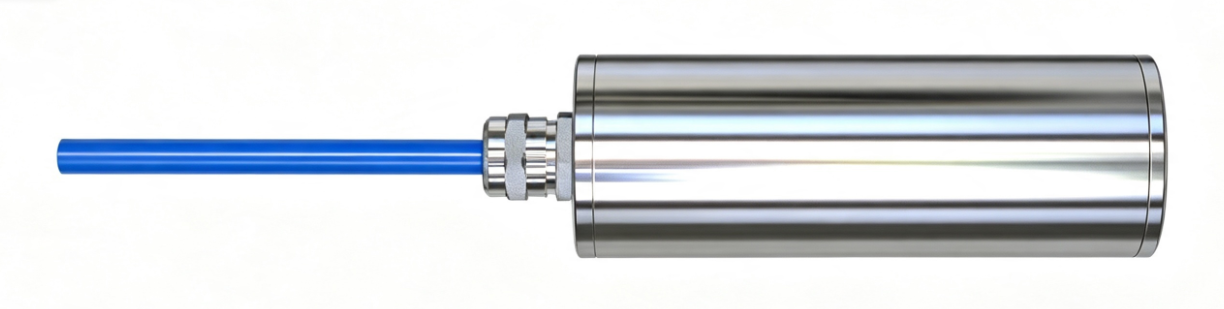
vibrating wire piezometer
Product Introduction
A vibrating wire piezometer is a sensor used to measure seepage water or static pressure. Changes in pore water pressure during construction serve as a basis for construction control; in regional stability analysis, the distribution of pore water pressure can be used as a basis for stability calculations .
Vibrating wire piezometers are suitable for measuring water pressure, such as seepage (phreatic line) and reservoir water level, in engineering projects such as dams, tunnels, roadbeds, and slopes. Vibrating wire piezometers can be permanently embedded in hydraulic structures or other concrete structures and soil to measure the seepage (pore) water pressure within the structure or soil. They can be buried at the interface of backfill and concrete, or embedded in boreholes or small-diameter pipes, or installed in piezometer tubes, boreholes, dam pipelines, and pressure vessels. By adding a temperature sensor, the temperature at the installation point can be measured simultaneously.
When paired with our company's vibrating wire sensor data acquisition unit, it can acquire real-time data from field sensors and convert it into corresponding physical quantities, which can then be uploaded via data transmission methods such as 485, 4G, NB-IoT, and LoRa .
n Designed using vibrating wire theory and manufactured with an all-stainless steel structure;
n It has advantages such as high sensitivity and accuracy, good linearity and stability;
n It is sensitive to concentrated loads, and its measurements are reliable and stable.
n Supports adding temperature detection functionality ;
n When paired with our company's vibrating wire sensor data acquisition unit, it enables real-time monitoring at the back-end terminal .
Temperature measurement | Temperature sensor can be installed, -25℃ to +60℃ |
Temperature accuracy | ± 0.2 ℃ |
Default line length | 2 meters |
Measurement range | 0MPa - 0.35MPa (other ranges are optional) |
≤0.08%F·S | |
Nonlinearity | ≤2%F·S |
Non-repetition | ≤0.5%F·S |
Comprehensive error | ≤2.5%F·S |
Greater than or equal to 1.2 times the full scale | |
Insulation resistance | ≥50MΩ |
Protection level | IP68 |
The main structure of a vibrating wire piezometer includes a permeable component, a sensing diaphragm, a signal transmission line, a vibrating wire, and an excitation electromagnetic coil. When water pressure acts on the sensor, it causes a change in the tension of the vibrating wire inside the sensor, which in turn changes the vibration frequency of the wire. By measuring the frequency of the vibrating wire, the internal water pressure value of the soil can be accurately calculated.
Equipment list:
■ 1 main device
■ Certificate of conformity, warranty card, etc.
Equipment dimensions:
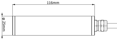
Note: The dimensions are the theoretical dimensions corresponding to our company's default measurement range. There may be slight differences between some measurement ranges and actual dimensions.
Equipment installation:
Vibrating wire piezometers have a wide range of applications, and the working and installation conditions vary. Please contact our factory if needed . Each piezometer comes with a testing certificate, which shows the relationship between the reading and the load, as well as parameters such as the initial zero reading and instrument coefficients. Upon arrival, the instrument should be checked for readings immediately. The readings should match the initial frequency at the factory ( error ≤ ±20Hz ). Installation can only proceed if the sensor readings are normal.
Installation Notes :
l Vibrating wire piezometers should be handled with care during installation to avoid collisions or drops.
l Before installation , check the readings of the instruments and equipment. If any instrument has abnormal readings, do not open it for repair.
l a vibrating wire piezometer : The permeable plate of the piezometer has a certain density. Pressurized water must pass through the permeable plate to act on the sensing membrane. If the water storage cavity between the permeable plate and the sensing membrane is not filled with water ( containing air bubbles ) , it will cause a serious lag in the piezometer reading . Before installation, the permeable plate and water storage cavity of the piezometer must be soaked to remove air.
l the vibrating wire piezometer is installed, it should be measured in time to confirm whether the piezometer is intact. Medium and coarse sand should be filled into the hole, and water should be poured into the hole to saturate it. Concrete should be poured on the upper part of the measuring hole.
l When using drilling for installation, mud should not be used to protect the hole wall; the drill hole should be straight and clean.
l At the specified depth, water-stopping measures should be taken to ensure that groundwater from the previous step does not intrude.
The following description focuses on the installation of the measurement equipment:
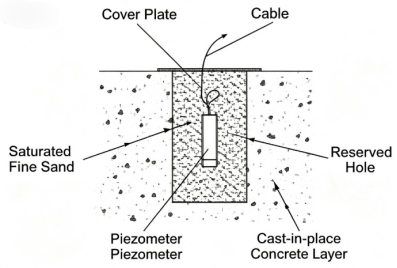
Embedded in concrete
Piezometers are embedded in cast-in-place concrete, typically at the construction joints of concrete blocks during layered pouring. They are primarily used to monitor the seepage pressure along the concrete construction joints under the influence of reservoir water.
Once the concrete pouring layer reaches the design elevation for the piezometer, dig a pit 30cm deep and 20cm in diameter on the base surface at the installation location. Fill the pit with medium-fine sand, place the soaked piezometer in the medium-fine sand inside the hole, and then fill it with more medium-fine sand. Lead out the observation cable according to the design route and pour concrete.
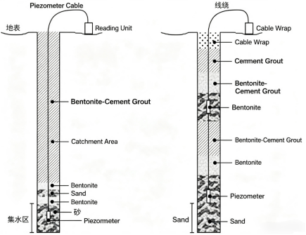
The laying of earth-rock dams
Before installing a piezometer under the concrete slab of the dam foundation, a hole should be drilled first to measure the hole depth and clean the borehole. Before installation, the piezometer should be placed in a permeable sandbag filled with medium to fine sand, or wrapped with permeable geotextile.
Pour medium to fine sand into the lower part of the piezometer installation area, and then lower the sandbag containing the piezometer into the hole. If the hole is too deep and the weight of the sandbag and cable exceeds the cable's strength, use steel wire to secure the piezometer and tie the cable to the wire for hoisting. This will prevent damage to the cable.
If it is necessary to observe the seepage water pressure in layers, multiple piezometers can be buried in one hole. The burial method is to repeat the above process step by step, and pay attention to the sealing and isolation between adjacent piezometers.
P=K( )
When the calculation result is positive, the instrument is under pressure.
Parameter description:
P: Load on the object being measured (MPa)
f0 : Initial measured frequency value (Hz )
f <sub>i</sub> : Real-time measured frequency value (Hz)
1. How to select the range of a vibrating wire piezometer?
According to the principle of selecting the measurement range, taking the "Technical Standard for Testing of Building Foundation Pit Engineering" (GB50497-2019) as an example, the instrument's measurement range should preferably be twice the sum of the hydrostatic pressure and the estimated excess pore water pressure.
2. What are the requirements for the installation location and quantity?
The relevant specifications and construction design drawings shall prevail.
3. How to measure the initial value of the piezometer?
The instrument should have its initial frequency measured before installation and compared with the factory initial frequency. If the difference is too large, it needs to be recalibrated.
The "Technical Standard for Monitoring of Building Foundation Pit Engineering" (GB50497-2019) stipulates that the initial frequency of the instrument should be measured before installation and compared with the factory initial frequency. If the difference is too large, the pore water pressure gauge needs to be recalibrated.
The initial frequency of the sensor should be collected before the sensor is installed. The initial water pressure value should be collected after the sensor is installed, one week before the foundation pit is excavated, or before the foundation pit dewatering begins. It is advisable to measure it daily for more than one week, and collect it three times consecutively when the data is stable, and take the average value.
4. What factors affect the reading of frequency data on site?
Environmental factors, improper installation methods, and sources of electrical noise interference.
5. How are alarm thresholds defined?
The relevant standards and construction design requirements should be followed. Taking the "Technical Standard for Testing of Building Foundation Pit Engineering" (GB50497-2019) as an example, for foundation pit engineering with safety levels of I and II (including III), the support alarm values are 60%~80% and 70%~80% of the ultimate bearing capacity design value, respectively.
Warning: Risk of personal injury. This equipment must not be used as a safety device or emergency stop device, nor for any other purpose that may result in personal injury due to equipment malfunction. Usage Restrictions: Use only for the intended authorized purpose . Consult the technical manual before installation, operation, or maintenance. Failure to comply with the above guidelines may result in death or serious injury.
The warranty period is 12 months from the date of purchase (based on a valid proof of purchase). During the warranty period, if the equipment itself malfunctions due to problems with the materials and workmanship of its components under normal use and maintenance, and the problem is verified, our company will provide free repair and replacement of parts.
Even after the warranty period, lifetime repair service is provided.
The warranty does not cover any of the following conditions:
1. The product is damaged due to incorrect installation, use, or operation.
2. Any parts of the equipment have been disassembled, repaired, modified, altered, or replaced by personnel other than our company's technicians, or by the user themselves.
3. Damage caused by negligence or by water or other substances entering the equipment.
4. Malfunctions or damages caused by unexpected events or natural disasters.
5. Faults or damage caused by operating parameters exceeding the range listed in the product specifications.


Long Press to Scan QR Code
Scan QR Code