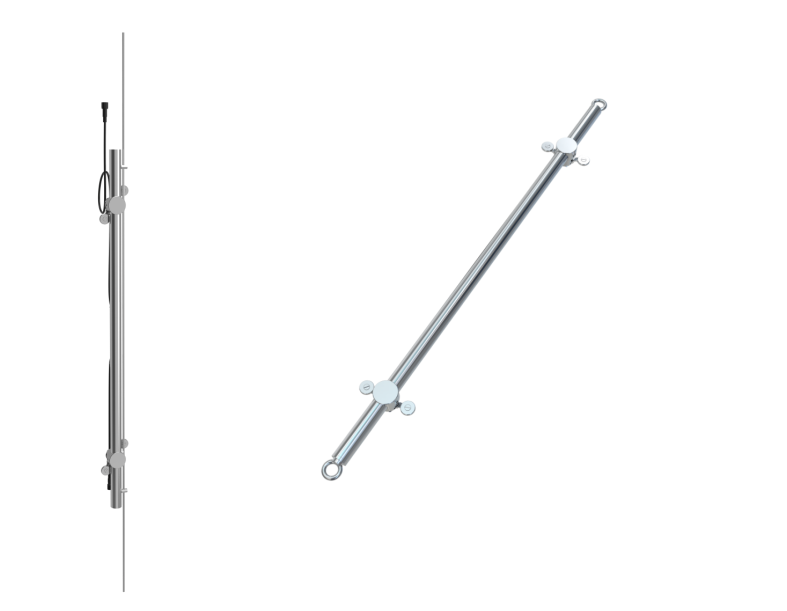
Inclinometer
Document Version: V1.5
1. Product Introduction
The inclinometer uses a gravity acceleration sensor as its sensing element, providing high measurement accuracy. It is widely used to observe horizontal displacement changes within soil and piles in earth-rock dams, embankments, building foundations, mines, foundation pit excavation, and rock and soil slopes. It can automate tilt measurement, and by installing multiple fixed inclinometers in a borehole, tilt changes can be monitored more accurately. It is an essential precision measuring instrument for engineering construction monitoring.
The output signal type is RS485, and the communication uses the MODBUS-RTU communication protocol . The maximum communication range is 2000 meters , and secondary development is supported.
n The product has a built-in reliable, high-resolution, and high-precision gravity acceleration chip.
n The product has a built-in high-precision temperature chip that provides full-range temperature compensation, effectively resisting environmental interference.
n 485 communication enables long-term automated measurement.
n It can upload data such as X-axis angle, Y-axis angle, and ambient temperature in real time.
Measurement range | ± 90 ° |
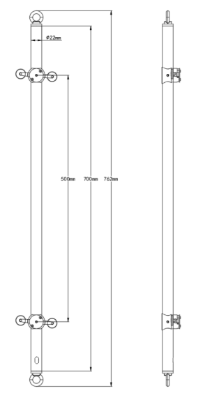
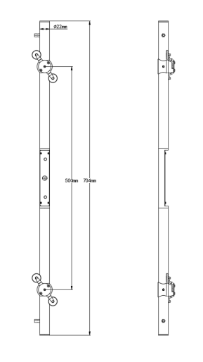
Side rod diameter | 22mm |
Guide wheel spacing | 500mm |
General | 700mm |
Measurement accuracy | ± 0.01 ° |
resolution | 0.001 ° |
Operating voltage | Wide voltage DC10-30V |
Operating temperature | -30 ℃ — + 70 ℃ |
Water pressure resistance | Pressure at a water depth of 300m |
Output signal | 485 |
60mm-80mm |
The performance data presented above was obtained under testing conditions using our company's testing system and software. In order to continuously improve our products, our company reserves the right to change design features and specifications without prior notice.
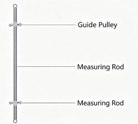
① The fixed inclinometer consists of a measuring rod, guide wheel, observation cable, connecting steel wire rope, etc.
Structural diagram
Dimensions
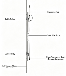
② The series fixed inclinometer consists of a measuring rod, guide wheel, black waterproof line, connecting steel wire rope, etc.
2.2.1 Calculation instructions
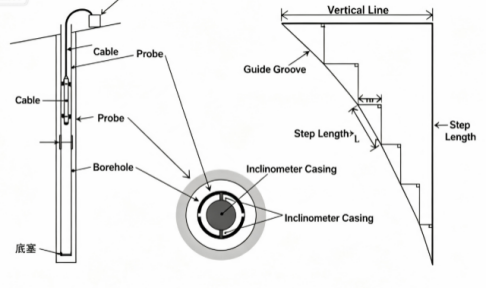
Inclinometers calculate the horizontal displacement of the measured structure at different depths by measuring the change in the angle between the axis of the inclinometer tube and the plumb line. Multiple fixed inclinometers can be installed in series at different depths within the inclinometer tube, and the measurement data can be analyzed to determine the displacement change of the measured unit over a period of time.
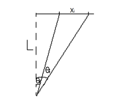
Xi = L * ( sinθi - sinθ0 )
S = Σ X i = X 1 + X 2 + ……
L: Step size, which is the step size of a measurement point at a certain depth, and is the distance between two measurement points.
θ : The change in angle at a certain depth, the angle between the measuring rod and the plumb line.
θ0 : The offset angle of the initial position.
X: The change in displacement at a certain depth, the difference between the current position and the initial position.
S: The horizontal displacement of the measured unit.
Calculations show that the change S of the ground position relative to the previous position is equal to the sum of the displacement changes of each position at different depths relative to the initial position.
2.2.2 Data Description
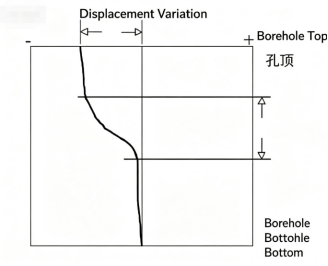
After collecting the displacement data of each segment of the inclinometer, a displacement-depth curve can be plotted to visually observe the displacement change of the measured soil. The displacement of each segment is the single-point displacement change of the inclinometer at each depth, and the sum of these values is the horizontal displacement change of the measured soil.
Equipment list:
■ Main Equipment
■ Certificate of Conformity, Warranty Card
■ Installation accessories (steel wire rope, observation cable, 704 glue)
3.2 Equipment Installation and Precautions
Please check before installation.
Please remove the equipment from the packaging box and check whether the equipment is in good condition, whether the accessories are complete, whether the accessories are intact, and whether the label address matches the remarks.
Wiring Precautions for Series Inclinometer Equipment
If water accumulates in the oblique bore after on-site installation, waterproofing treatment must be applied to the equipment connectors. After the connectors are plugged in, they must be sealed with waterproof adhesive. The waterproof connectors between equipment should be treated as shown in the diagram below.
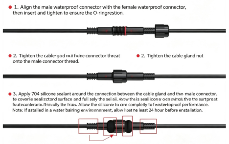
Equipment Installation Precautions
(1) Note: If water accumulates in the oblique hole after on-site installation, waterproofing treatment must be done at the equipment connector. After the connector is plugged in, waterproof sealant should be used to seal it. (Note: The cap of the plug, the connection point with the wire, and the hole should be fully coated, as shown in the picture above.)
(2) Drill holes at the location to be measured and install inclinometer tubes. When splicing and installing inclinometer tubes, the bottom should be sealed and the inclinometer tubes should be installed vertically.
(3) Backfilling can begin once the inclinometer tube installation is confirmed to be in good condition. Backfill typically uses bentonite balls or native soil and sand. Water should be injected every 3-5 meters during backfilling to ensure the bentonite balls or native soil and sand adhere firmly to the borehole wall. This process should continue until the borehole opening is reached. Exposed sections of the inclinometer tube above the ground should be protected by covering them with caps to prevent objects from falling in. The surface section of the inclinometer tube should be cast into a concrete pier to protect the stability of the opening and its corners. Observation points should be set up on the pier.
(4) When installing the inclinometer tube, the guide groove should be aligned with the measurement direction. The direction of the high guide wheel of the inclinometer is the X+ direction. When installing the inclinometer, the X+ direction should be aligned with the measurement direction and placed into the inclinometer tube along the guide groove.
(5) According to the site requirements, it is necessary to use steel wire rope or connecting screw to suspend the inclinometer in the inclinometer tube. When multiple inclinometers or series fixed inclinometers are placed, the direction of the guide wheel should be consistent. Cut the steel wire rope according to the design requirements and reserve settlement space at the bottom of the inclinometer tube.
(6) Note that the cable should be slack after it comes out, and should not be taut.
(7) After installation, the data can be read through the configuration software or uploaded to the platform for reading .
Power supply and wiring
The power input voltage is wide, DC10-30V . When wiring the 485 signal lines , ensure that lines A and B are not reversed, and that addresses do not conflict between multiple devices on the bus.
1) There are certain specifications for 485 field wiring. Please refer to the document package " 485 Equipment Field Wiring Manual " for details.
2) When devices are connected to the 485 bus , ensure that the addresses of multiple devices are not duplicated.
Specific wiring ( divided into fixed type and series type )
| Line color | illustrate |
electricity source | Red ( brown ) | Positive power supply ( wide voltage 10-30V DC) |
black | Power supply negative | |
Pass letter | White (yellow) | 485 -A |
Green ( blue ) | 485 -B |
Editor code | 8 -bit binary |
Data bits | 8 -bit |
Parity bit | none |
Stop bit | 1 person |
Error Validation | CRC (Cyclic Redundancy Code) |
baud rate | 1200 bit/s , 2400 bit/s, 4800 bit/s , 9600 bit/s , 19200 bit/s , 38400 bit/s , 57600 bit/ s , or 115200 bit/s ; the factory default is 4800 bit/s. |
The Modbus- RTU communication protocol is adopted , and the format is as follows:
Initial structure ≥ 4 bytes of time
Address code = 1 byte
Function code = 1 byte
Data area = N bytes
Error check = 16 -bit CRC code
End structure ≥ 4 bytes of time
Address code: This is the address of the transmitter, which is unique in the communication network (factory default is 0x01 ).
Function code: Function indication of the command issued by the host.
Data area: The data area contains the actual communication data. Note that the high byte of the 16-bit data comes first!
CRC code: a two-byte checksum.
Host query frame structure:
Address code | Function code | Register start address | Register length | check code low byte | high byte of check code |
1 byte | 1 byte | 2 bytes | 2 bytes | 1 byte | 1 byte |
Slave response frame structure:
Address code | Function code | Valid byte count | Data Zone 1 | Data Zone 2 | Data N area | check code low byte | high byte of check code |
1 byte | 1 byte | 1 byte | 2 bytes | 2 bytes | 2 bytes | 1 byte | 1 byte |
Note that items marked with an asterisk (*) are newly added registers. Some devices do not have this register. If you require it, please contact our sales staff.
PLC or configuration address | content | operate | Definitions | |
00 00 H | 400 0 1 (decimal) | x-axis angle | Read-only | 32-bit signed integer, reads the x-axis tilt angle, magnified a thousandfold. High position |
00 01 H | 400 02 (decimal) | |||
0002H | 400 03 (decimal) | y-axis angle | Read-only | 32-bit signed integer, reads the y-axis tilt angle, magnified a thousandfold. High position |
0003H | 400 04 ( decimal) | |||
0004H | 400 05 ( decimal) | x-axis displacement | Read-only | 32-bit signed data, calculated from the X-axis angle and the length of the inclinometer beam, multiplied by 100, unit mm. |
0005H | 40006 ( decimal ) | |||
0006H | 40007 ( decimal ) | temperature | Read-only | Read the temperature value, magnify it tenfold, and use °C as the unit. |
0009H | 40010 (decimal) | Software version | Read-only | Software version number |
00A0H 00A5H | 40161 (decimal) 40166 (decimal) | Product Model | Read-only | There are six registers in total; ASC displays the product model. |
00C7H | 40200 (decimal) | Length of Inclined Beam | Reading and writing | Initial value 500mm, unit mm |
00C8H | 40201 (decimal) | x-axis deviation value | Reading and writing | 32-bit signed integer, magnified a thousandfold High position |
00C9H | 40202 (decimal) | |||
00CAH | 40203 (decimal) | y-axis deviation value | Reading and writing | 32-bit signed integer, magnified a thousandfold , only applicable to dual-axis and triaxial sensors. High position |
00CBH | 40204 (decimal) | |||
07D0 H | 42001 (decimal ) | Device address | Reading and writing | 1~254 (factory default 1) |
07D1H | 42002 (decimal) | Device baud rate | Reading and writing | 0 represents 2400 1 represents 4800 2 represents 9600 3 represents 19200 4 represents 38400 5 represents 57600 6 represents 115200 7 represents 1200 |
07D7 | 42008 (decimal) | Parity check | Reading and writing | Parity 0 (no parity), parity 1 (odd parity), parity 2 (even parity). Setting numbers other than 0, 1, and 2 will be treated as having no parity (0). |
005A | 40090 (decimal) | Determine the initial angle | Reading and writing | Write 5A5A to determine the initial angle for displacement calculation. |
X-axis angle values at device addresses 0x00 and 0x01 .
Query Frame
Address code | Function code | Starting address | Data length | check code low byte | high byte of check code |
0x 01 | 0x0 3 | 0x00 0x 00 | 0x00 0x0 2 | 0x C4 | 0x 0 B |
Response frame
Address code | Function code | Return the number of valid bytes | x-axis angle | check code low byte | high byte of check code |
0x 01 | 0x0 3 | 0x0 4 | 0x0 0 0x 01 0x 02 0x 34 | 0x AB | 0x44 |
X-axis angle calculation:
X-axis angle : 0001 0234 H (hexadecimal) = 66100 => x-axis angle = 66.100°
Y-axis angle values from device addresses 0x02 and 0x03 .
Query Frame
Address code | Function code | Starting address | Data length | check code low byte | high byte of check code |
0x 01 | 0x0 3 | 0x00 0x 02 | 0x00 0x0 2 | 0x 65 | 0x C B |
Response frame
Address code | Function code | Return the number of valid bytes | Y-axis angle | check code low byte | high byte of check code |
0x 01 | 0x0 3 | 0x0 4 | 0x FF 0x FF 0x 53 0x 69 | 0x 06 | 0x C9 |
Y-axis angle calculation:
Y-axis angle : FFFF 5369 H (hexadecimal) = -44183 => Y-axis angle = -44.183°
5 . Common problems and solutions
Possible reasons:
1) The computer has multiple COM ports, and the wrong port was selected.
2) The device address is incorrect, or there are devices with duplicate addresses (the factory default is all 0x01 ).
3) Baud rate, parity check, data bits, stop bits errors.
4) The 485 bus is disconnected, or the A and B lines are reversed.
5) If there are too many devices or the wiring is too long, power should be supplied nearby, a 485 power booster should be added, and a 120Ω terminating resistor should be added.
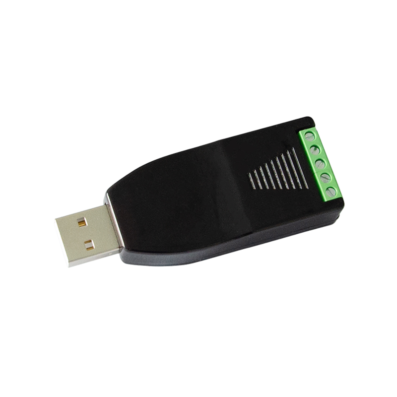
6) The USB to 485 driver is not installed or is damaged.
7) Equipment damage.
1. Warning: Risk of personal injury. This equipment must not be used as a safety device or emergency stop device, nor for any other purpose that may result in personal injury due to equipment malfunction. Usage Restrictions: Use only for the intended authorized purpose . Consult the technical manual before installation, operation, or maintenance. Failure to comply with the above guidelines may result in death or serious injury.
2. This product is a precision instrument and should be protected from drops and impacts.
3. After installation, ensure that the pull line is perpendicular to the outlet and that the wire rope is pulled out as perpendicularly as possible to ensure measurement accuracy.
4. If the instrument malfunctions due to drops or other reasons, please contact our technicians. Do not disassemble the instrument yourself.
5. Lightning protection measures should be taken for the orifice and observation cable of the guide wheel type fixed inclinometer, especially in areas with high incidence of lightning strikes.
6. Please read the equipment installation instructions and precautions carefully during the product installation process.
6. Warranty Statement
The warranty period is 24 months from the date of purchase (based on a valid proof of purchase). During the warranty period, if the equipment itself malfunctions due to problems with the materials and workmanship under normal use and maintenance, and the problem is verified, our company will provide free repair and replacement of parts.
Even after the warranty period, lifetime repair service is provided.
The warranty does not cover any of the following conditions:
1. The product is damaged due to incorrect installation, use, or operation.
2. Any parts of the equipment have been disassembled, repaired, modified, altered, or replaced by personnel other than our company's technicians, or by the user themselves.
3. Damage caused by negligence or by water or other substances entering the equipment.
4. Malfunctions or damages caused by unexpected events or natural disasters.
5. Faults or damage caused by operating parameters exceeding the range listed in the product specifications.


Long Press to Scan QR Code
Scan QR Code