Pull-rod crack gauge
File version: V1.3
With the increasing complexity and scale of modern engineering structures, higher requirements are placed on the safety, stability, and durability of these structures. Cracks, as one of the most common forms of damage to structures, often foreshadow potential safety hazards. A tension-wire crack gauge is a displacement measurement device specifically designed to monitor changes in crack width and tilt angle in structures such as bridges, dams, buildings, and tunnels.
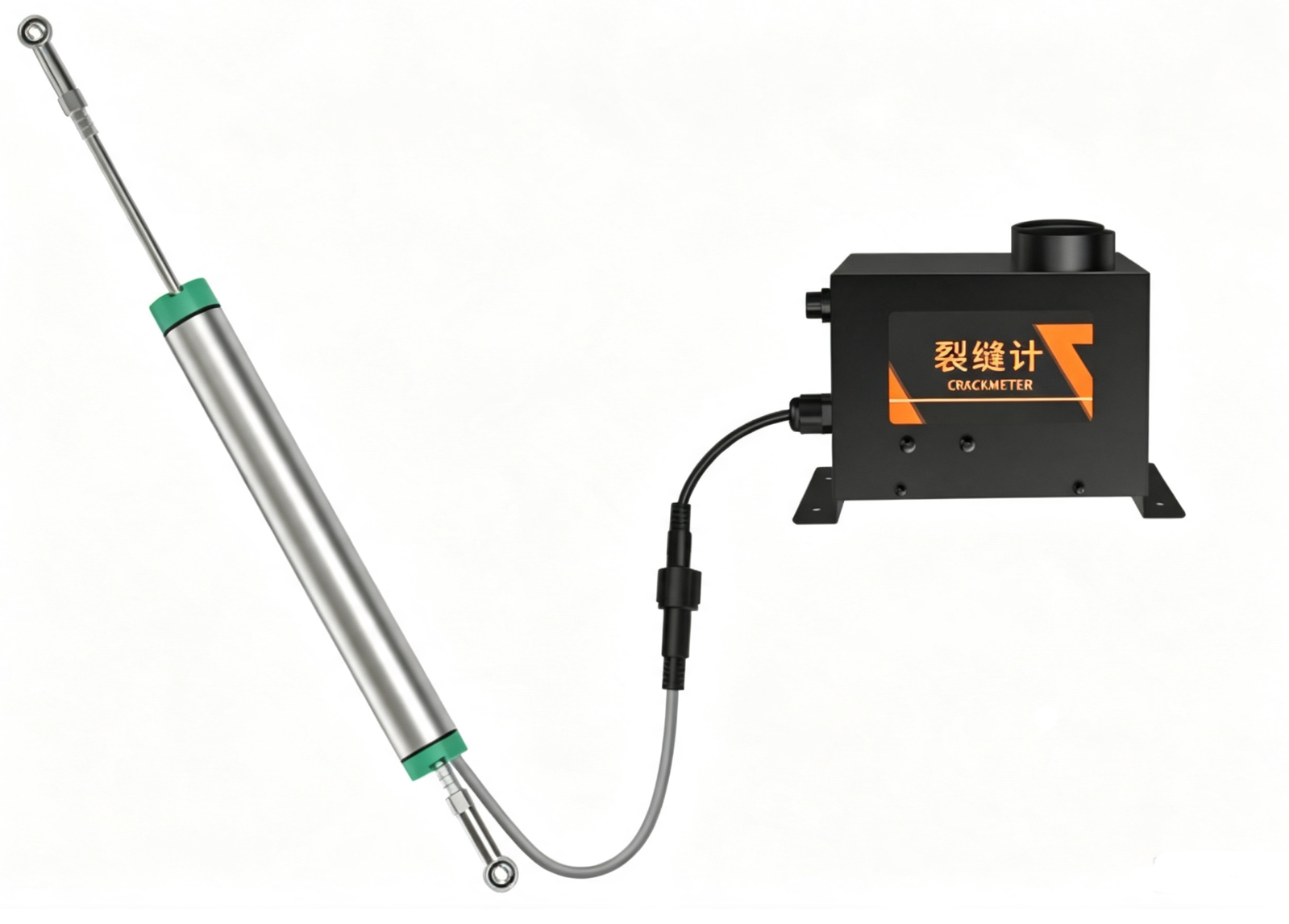
This device measures crack displacement by extending and retracting a lever, converting the mechanical displacement into an electrical signal output. It is suitable for long-term monitoring and real-time data acquisition. The lever-type crack gauge features a simple structure, easy installation, and good stability. Measurement data is uploaded to a LORA gateway via LORA wireless communication. The LORA gateway then transmits relevant information to the backend server via a 4G/ETH communication module. The entire process is wiring-free and has low power consumption. Users can view monitoring data anytime, anywhere on their mobile phones or computers. This product is powered by a built-in battery; a single battery replacement allows for two years of continuous use, and on-site installation is simple and requires no wiring.
n The device is designed for low power consumption .
n It can detect crack changes and the tilt angle of the installation position in real time and output alarm information in a timely manner .
n The sensor part has an aluminum alloy shell , which is well sealed and prevents rainwater from corroding the environment for a long time .
n The front and rear spherical hinges allow for free and quick installation.
n It can be used with LORA repeaters to extend the communication distance.
n Each device has a unique address, making it easy to manage and identify, and it can be used with various software platforms provided by our company.
n Device parameters can be configured via Bluetooth on a mobile phone, which is simple and convenient.
powered by | Built-in battery powered |
Device power consumption | 7.6mW (default interval) |
Crack measurement range | 0~100mm |
Crack measurement accuracy | 0.05% |
Crack measurement resolution | 0.1mm |
Inclination measurement range | X-axis -180°~180°, Y-axis -90°~90° |
Inclination measurement accuracy | Static accuracy 0.1°, dynamic accuracy ±0.5° |
Tilt measurement resolution | 0.01° |
Upload interval | The default upload interval is 60 minutes, and the shortest upload interval can be set to 1 minute. |
Operating temperature | -35~60℃ |
Operating humidity | ≤95% |
Equipment list:
n Pull-rod crack gauge
n M8 expansion bolts * 4
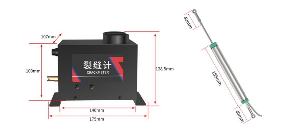
The fisheye mounting hole has a diameter of 4mm. Customers can choose appropriate fixing materials according to the site conditions to fix the mounting holes on both sides of the rod sensor device to the two sides of the measurement point.
Before installation, the ground must be hardened with cement or a hard medium .
The data acquisition unit is secured with expansion screws. Note that the unit should be installed horizontally rather than with the bottom facing up.
Notice:
(1)When the Y-axis is around 90 degrees, it is the Euler angle blind zone of the device. At this time, the X output angle is inaccurate. When installing the monitoring host, care should be taken to avoid this angle.
(2) When the equipment needs to be powered off and restarted, unscrew the equipment switch, remove the fuse, wait 30s-40s, and then screw the fuse back in to power on.
Coefficient A: Crack distance coefficient A.
Coefficient B: Crack distance coefficient B.
Inclination calibration coefficient K: Inclination calibration coefficient K.
Inclination calibration coefficient B: Inclination calibration coefficient B.
The device's 8-bit address: The 8-bit device address corresponding to the LoRa host.
Data Acquisition Module Channel 1 Device Source: Measurement Point Address, used to distinguish measurement points. The default value is 1, and it can only be modified between 1 and 254. If it exceeds this range, the original value will remain unchanged.
Transmit Channel for Acquisition Module 1: Channel settings support 1-64. If paired with a host , the channel settings must match the host 's "Receive Channel for Acquisition Module". Note: Transmit and receive channels for different modules under the same gateway cannot be the same. If multiple gateways are in the same area, the channel parameters for each gateway cannot be the same. If the default number of channel groups is insufficient, custom channel expansion is supported .
Acquisition Module 1 Receive Channel: Channel settings support 1-64. If paired with a host , the channel settings must match the host 's "Acquisition Module Transmit Channel". Note: Different modules under the same gateway must have different transmit and receive channel settings. If multiple gateways are in the same area, their channel parameters must be different. If the default number of channel groups is insufficient, custom channel expansion is supported .
Spreading factor for the acquisition module: Enter the range 7-9, default 9. Modification is not recommended. The corresponding controller spreading factor should be consistent with the host. The spreading factor setting affects data transmission speed, power consumption at the measurement point, and transmission distance in the communication system (distance test conditions: open, unobstructed environment, tested with our company's suction cup antenna ; power consumption comparison: for reference only ) .
The relationship between the increase in the number of relays and the transmission distance for each additional second in the time slot interval. | |||
| Spreading factor 7 | Spreading factor 8 | Spreading factor 9 |
Increase the number of relays | 3 units | 2 units | 1 unit |
Transmission distance (line of sight) | 2000m+ | 2300 meters+ | 3000 meters+ |
Increased power consumption at measurement points | +0.25mA | +0.10mA | -- |
Time Slot Interval: This parameter is for viewing only. It represents the upload interval between adjacent measurement points. A longer interval results in a more stable communication system and longer battery life for the corresponding measurement point, but it also increases the data update cycle. The default value is 3000 milliseconds. If you need to shorten the interval, please contact our technical staff to determine its feasibility. An inappropriate parameter here may affect the stability of the communication system .
Number of measurement points: This parameter is only for viewing. The value is the number of measurement points set by the host + 8. The number of external measurement points connected to the host varies depending on the host model . If the slave address value of host channel 1 exceeds this value - 8, the measurement point will enter sleep mode and stop sending data .
Wireless sleep time for the host device: The time it takes for the device to upload data. Please enter a multiple of 60 here. If the number is less than a multiple of 60, the device will delay the data upload time to a multiple of 60.
1)Warning: Risk of personal injury. This equipment must not be used as a safety device or emergency stop device, nor for any other purpose that may result in personal injury due to equipment malfunction. Usage Restrictions: Use only for the intended authorized purpose . Consult the technical manual before installation, operation, or maintenance. Failure to comply with the above guidelines may result in death or serious injury.
The warranty period is 12 months from the date of purchase (based on a valid proof of purchase). During the warranty period, if the equipment itself malfunctions due to problems with the materials and workmanship of its components under normal use and maintenance, and the problem is verified, our company will provide free repair and replacement of parts.
Even after the warranty period, lifetime repair service is provided.
The warranty does not cover any of the following conditions:
1. The product is damaged due to incorrect installation, use, or operation.
2. Any parts of the equipment have been disassembled, repaired, modified, altered, or replaced by personnel other than our company's technicians, or by the user themselves.
3. Damage caused by negligence or by water or other substances entering the equipment.
4. Malfunctions or damages caused by unexpected events or natural disasters.
5. Faults or damage caused by operating parameters exceeding the range listed in the product specifications.
Appendix 1
Factor numbering | Factor meaning | illustrate |
0 | Crack distance | 16-bit unsigned |
1 | X-axis tilt angle | 16-bit unsigned |
2 | Y-axis tilt angle | 16-bit unsigned |


Long Press to Scan QR Code
Scan QR Code